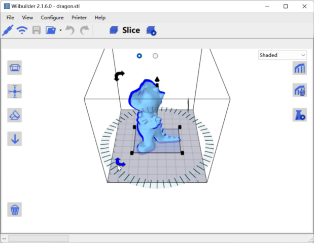
6.WIIBUILDER SLICING SOFTWARE
 Models processed in slicing software to generate Gcode files for
printing.
Models processed in slicing software to generate Gcode files for
printing.
3D printing process:
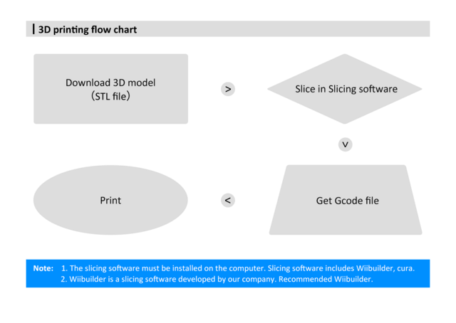
Slicing software installed on computer. Common options: Wiibuilder, Cura. Wiibuilder developed in-house, user-friendly, recommended.
Wiibuilder included on printer's TF card. Use card reader to view TF contents on PC for installation.
System requirements for Wiibuilder:
-
CPU: Pentium 1GHz
-
RAM: 1GB minimum
-
Disk: 1GB+ free space
-
Display: 640x480 minimum
-
Graphics: 3D acceleration, OpenGL 2.0+
-
Color: 256 colors minimum
-
OS: Windows 7+ / MacOS 10.13.6+
-
Other: .Net Framework 4.5.2+
Installation
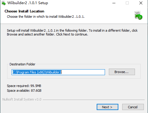
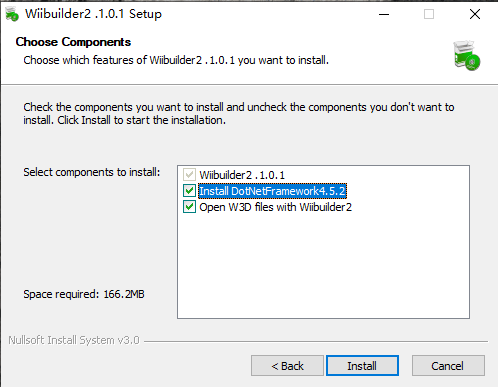
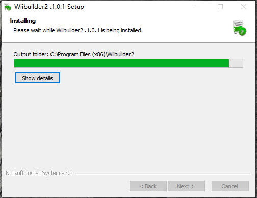
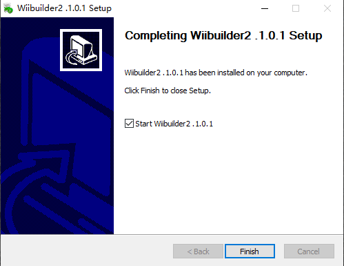
Installation on Windows
Steps to install Wiibuilder:
Locate and run Wiibuilder.exe on TF card. Click Install > Next > Finish to continue.
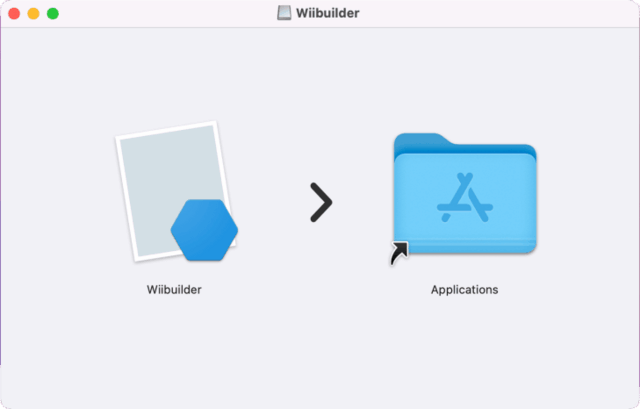
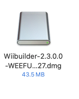
Installation on MacOS
OS: MacOS 10.13.6+
Decompress installer. Double-click package, drag Wiibuilder to Applications.
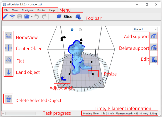
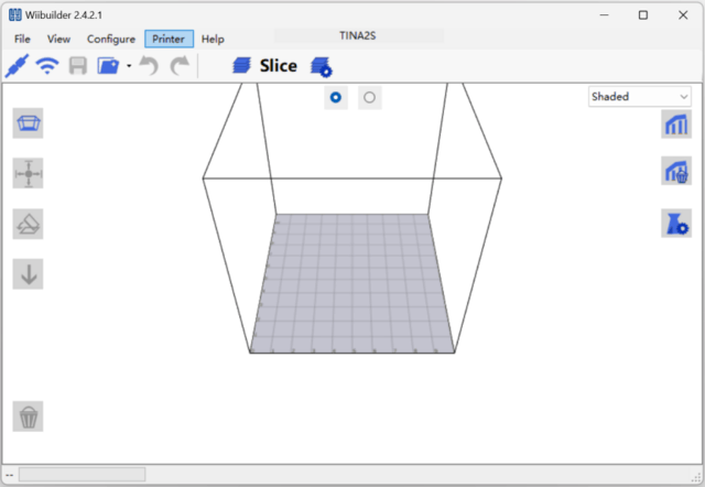
Interface Introduction
-
Menu Bar: Access Wiibuilder menu
-
Toolbar: USB/WiFi connect, save Gcode, load model, undo/redo, slice, settings
-
Home View: Restore default view angle
-
 Center Object: Auto-adjust model XY
to center on platform
Center Object: Auto-adjust model XY
to center on platform -
Flat: Auto-flatten tilted model on platform
-
Land Object: Auto-adjust model Z to align bottom with platform
-
Delete Selected: Remove current model
-
Add/Delete Support: Manually add/remove model supports
-
Edit: Open model and Gcode editor
Right-click model for context menu: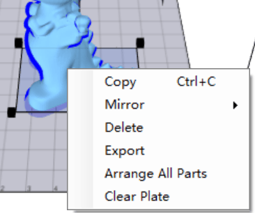
-
Copy model
-
Mirror on X/Y/Z axis
-
Delete model
-
Export model to STL
-
Arrange All Parts: Auto-adjust multi-model position and spacing
-
Clear Plate: Remove all models
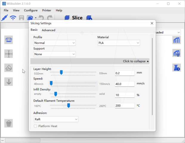
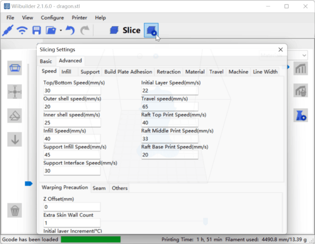
Slicing Settings:
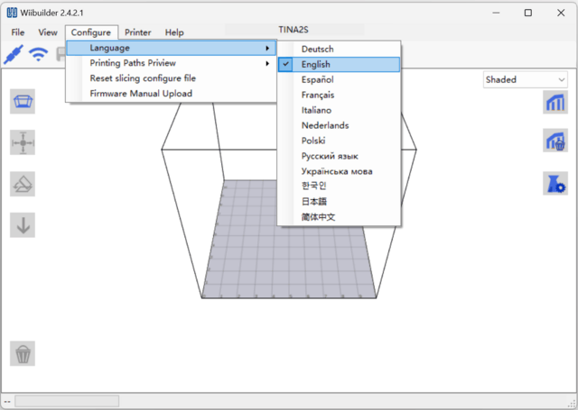
Select Language
Open Wiibuilder, click Configure > Language to select.
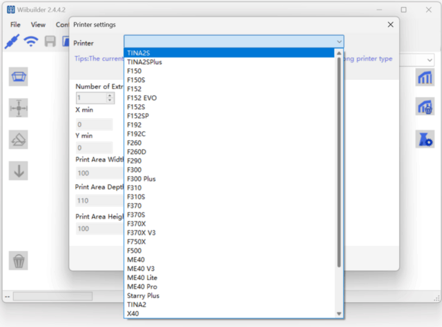
Select Printer
Click Printer to select model.
Click Printer.
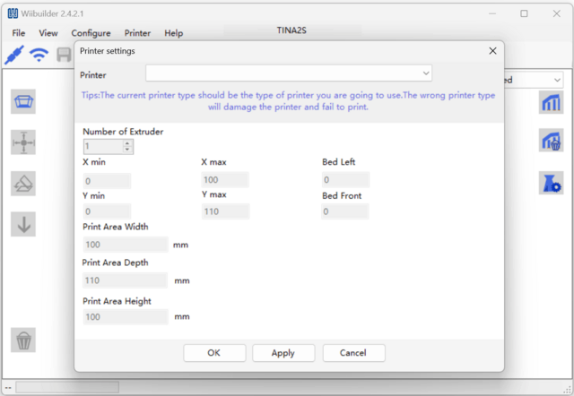
Scroll to find "TINA2S".Note: Not "TINA2", will fail if wrong.
Add Model
Open Wiibuilder, click File to load model or drag model in.
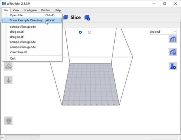
Five sample models in "Show Example Directory" for test printing.
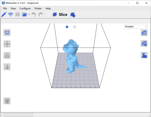
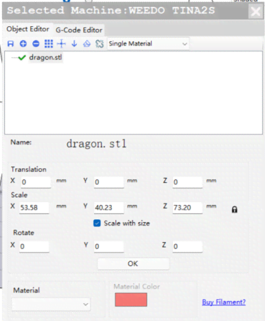
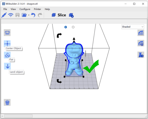
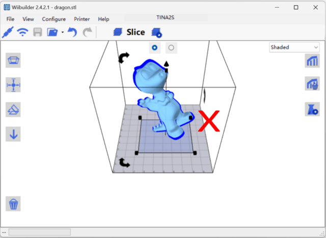
Adjust Model
Click model to adjust size, angle, position.
Model should be centered and properly placed on platform. Click Center Object, Flat, Land Object. If floating, print fails.
Basic Parameter Settings
Beginners use defaults without adjustment.
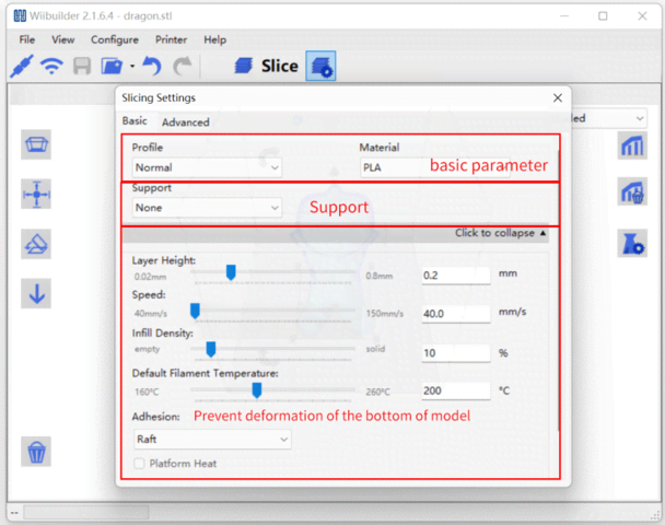
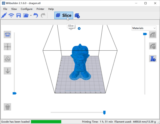
After setting parameters, click Slice to convert file.
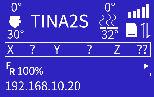
Send Files via Network
Note: The 3D printer has been connected to the network, and the IP address is displayed. For operations, Please refer to: "Print by app".
Select the computer to use the same network as the device. Using different networks can cause transfer failures.
The computer should connect to the same local network with the 3D printer.
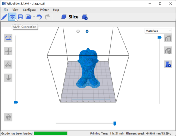
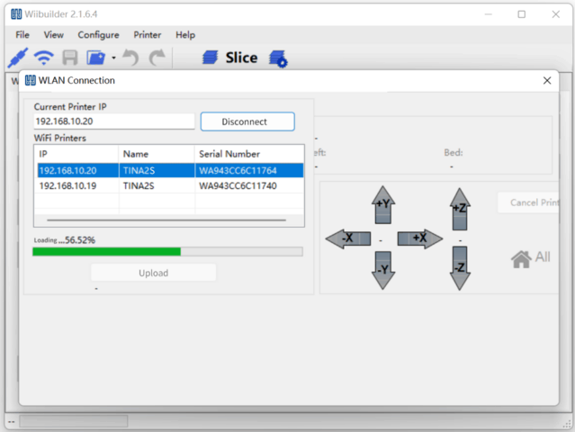
Click "WLAN Connection", the software will automatically search for the 3D printers in the local network and show them in the below list. If no 3D printer be found, you can also try to manually enter the IP address of the 3D printer to connect.
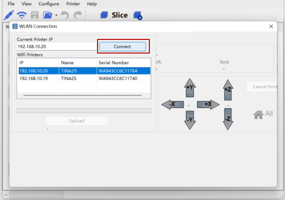
Note: If you still cannot connect to the 3D printer, please check whether the firewall of the computer prohibits the software from networking, and whether the computer and the 3D printer are in the same local area network.
Send the sliced model to the 3D printer, and the 3D printer starts printing after receiving it.
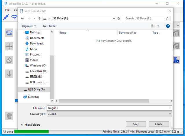
Send Files via TF Card
Save sliced model to TF card, insert card into printer.
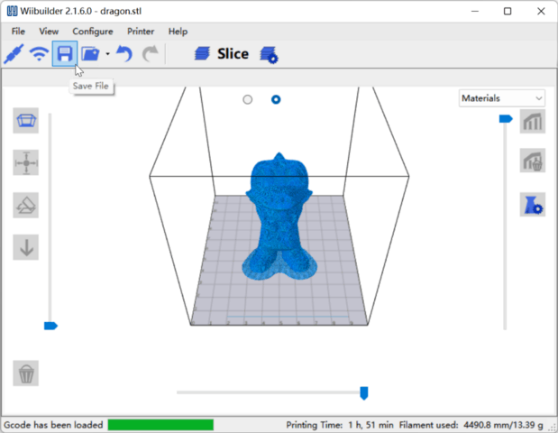
Note: Save directly to TF root, not in folder.

Advanced Parameter Settings
Speed Tab
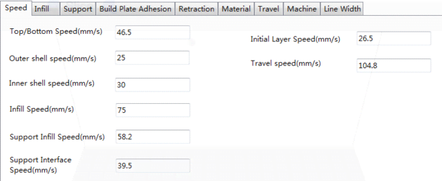
Options:
-
Top/Bottom Speed (mm/s): Top and bottom surface print speed
-
Outer/Inner Shell Speed (mm/s): External and internal shell surface print speed
-
Infill Speed (mm/s): Infill print speed
-
Support Infill/Interface Speed (mm/s): Support infill and top/bottom surface print speed
-
Initial Layer Speed (mm/s): First layer print speed
-
Travel Speed (mm/s): Non-print movement speed
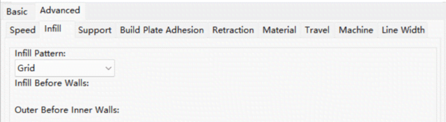
Infill Tab
-
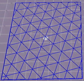
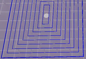
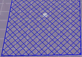
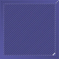
Infill Pattern: Select from Lines, Grid, Triangles, Zig Zag, Concentric, Cross, Octet. Patterns shown below.
-
Infill Before Wall: Print infill then walls.
-
Outer Before Inner Walls: Print outer then inner walls.
-
Infill Patterns:
| Infill Patterns | |
|---|---|
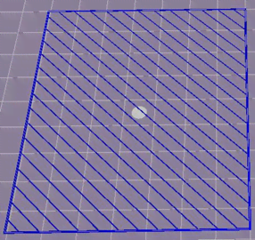 |
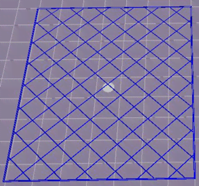 |
| Lines | Grid |
 |
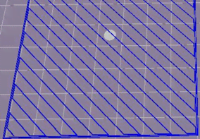 |
| Triangle | Zig Zag |
 |
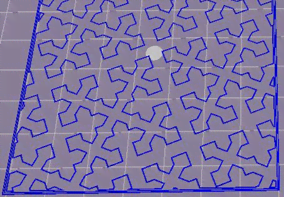 |
| Concentric | Cross |
 |
|
| Octet |
Support Tab
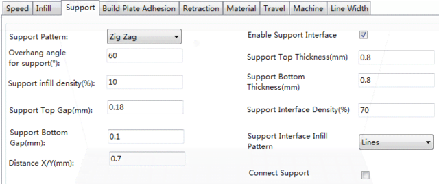
- Support Pattern: Select from Lines, Grid, Triangles, Zig Zag, Concentric. Same designs as infill patterns.
-
Lines easier to remove, for models needing more support
-
Grid for small models needing less support
-
Zig Zag stronger than Lines, better than Grid, for difficult to > remove supports
-
Overhang Angle: Angle between support and model surface. Larger = easier removal, smaller = better support. Default 60°.
-
Support Infill Density (%): Higher density = stronger support.
-
Support Top/Bottom Gap (mm): Distance from support top/bottom to model. Smaller = more effective but harder removal leaving.
-
residue, larger = less effective but easier removal for smoother surface.
-
Distance X/Y (mm): Horizontal distance from support to model, same effects as Top/Bottom Gap.
-
Enable Support: Use supports.
-
Support Top/Bottom: Top and bottom support layer thickness.
-
Support Interface: Infill percentage inside supports.
-
Support Interface Infill Pattern: Select from Lines, Grid, Triangles, Zig Zag, Concentric. Same designs as infill patterns.
-
Connect Support: Join separate supports into one.
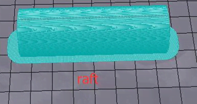
Build Plate Adhesion Tab
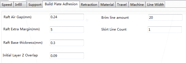
- Raft Air Gap (mm): Distance between raft and model, determines removal difficulty.
-
Raft Extra Margin (mm): Distance from raft edge to model surface.
-
Raft Base Thickness (mm): Raft thickness.
-
Initial Layer Z Overlap: Overlap between model's first and second layers.
-
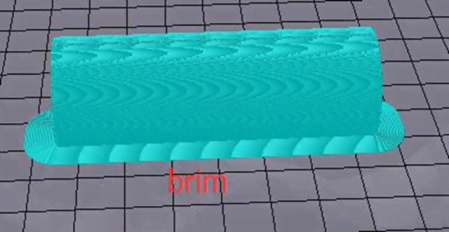
Brim Line Amount: Number of rings added to model edge contacting platform.
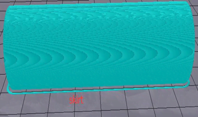
- Skirt Line Count: Number of anti-overflow lines at model end contacting platform.
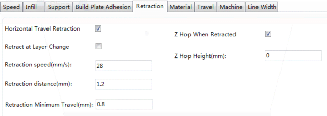
Retraction Tab
-
Horizontal Travel Retraction: Enable filament retract during non-print horizontal moves
-
Retract at Layer Change: Retract filament between layers
-
Retraction Speed (mm/s): Filament retract speed
-
Retraction Distance (mm): Filament retract distance inside nozzle
-
Retraction Minimum Travel (mm): Minimum pre-print nozzle move distance before retracting
-
Z Hop When Retracted: Enable nozzle lift after retract
-
Z Hop Height (mm): Nozzle lift distance after retract
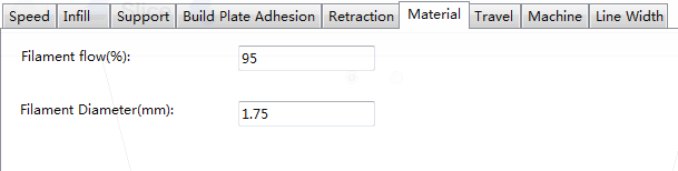
Material Tab
-
Filament Flow (%): Molten filament flow rate based on material. Generally 90 for PLA/PLA Pro, 100 for ABS.
-
Filament Diameter (mm): Diameter of filament used. Printer only supports 1.75mm.
Travel Tab
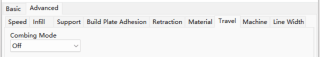
- Combing Mode: Nozzle movement when not printing.
-
Off: Shortest move from previous extrusion to new start
-
All: Move along already extruded paths
-
No Skin: Avoid outer layers moving to new start, improves quality
Machine Tab
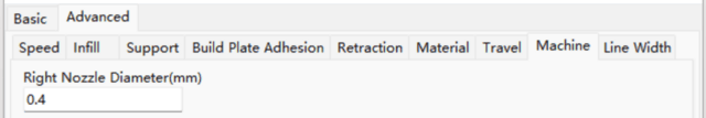
- Right Nozzle Diameter (mm): Diameter of right extruder nozzle. Printer has single right extruder with 0.4mm nozzle.
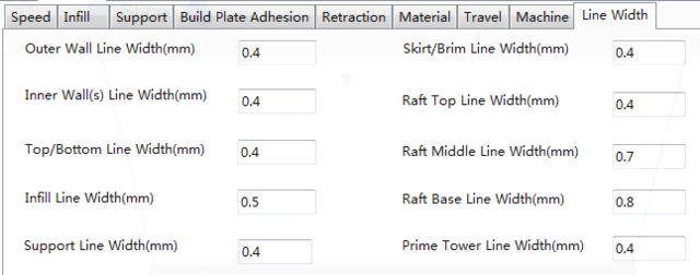
Line Width Tab
-
Outer Wall Line Width (mm): Outermost wall line width. Lower for finer detail.
-
Inner Wall(s) Line Width (mm): Single wall line width for all but outermost
-
Top/Bottom Line Width (mm): Top and bottom line width
-
Infill Line Width (mm): Single infill line width
-
Support Line Width (mm): Single support line width
-
Skirt/Brim Line Width (mm): Single skirt or brim line width
-
Raft Top Line Width (mm): Line width in raft top surface. Thin for smooth top.
-
Raft Middle Line Width (mm): Line width in middle raft layers. Thicker second layer for build plate adhesion.
-
Raft Base Line Width (mm): Raft base layer line width. Thick for build plate adhesion.
-
Prime Tower Line Width (mm): Prime tower extrusion width
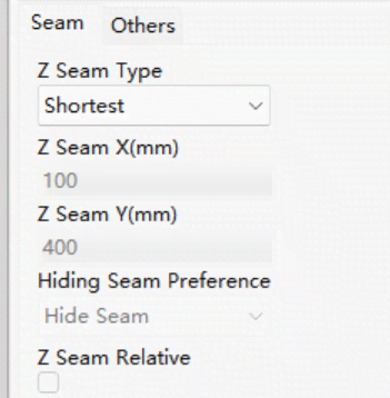
Seam Tab
Note: Z Seam is where printer finishes outer layer, may cause blob/zit when changing Z height. Aligned seams make noticeable line (Z Seam) from oozing at start/stop. Options minimize this.
- Z Seam Type: Determines Z Seam location
-
Shortest: Most time-efficient start/stop
-
User Specified: Set X/Y start/stop
-
Random: Random start/stop prevents column buildup
-
Sharpest Corner: Start/stop at sharpest model corner
-
Z Seam X/Y (mm): X/Y location of Z Seam. Only for User Specified type.
-
Hiding Seam Preference: For Sharpest Corner type, puts seam inside or outside corner
-
Z Seam Relative: Relative to object center or absolute on build plate. Only for User Specified type.
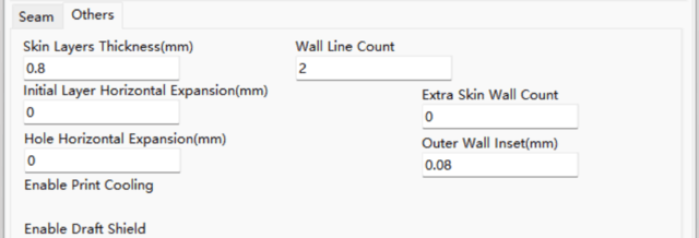
Others Tab
-
Skin Layers Thickness (mm): Top and bottom skin layer thickness
-
Horizontal Expansion (mm): Fine-tune part size to offset cooling shrinkage for tighter tolerances
-
Skin Alternate Rotation: Top/bottom layers change 90° each layer. This adds 45° rotation every 2 layers.
Normal top/bottom layer directions:
Layer 3 with Skin Alternate Rotation enabled:
-
Enable Print Cooling: Direct cooling air at printed part
-
Enable Draft Shield: Print wall around model to block external airflow. Used when Print Cooling off for longer cooling materials like ABS.
-
Wall Line Count: Number of walls to print